
RO4350B PCB manufacturing
RO4350B PCB Manufacturing, Rogers 4350B and FR4 Mixed medium PCBs Vendor, We offer Microtrace and Ultra-small gap Rogers series PCBs from 2 layer to 50 layers. fast shipping time. ans high quality.
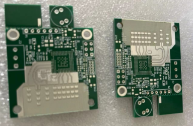
RO4350B PCBs are high-frequency printed circuit boards fabricated using RO4350B laminate material, renowned for its exceptional electrical properties and stability. With a dielectric constant (εr) of 3.48 and a dissipation factor (Df) of 0.0037 at 10 GHz, RO4350B is specifically engineered for applications demanding reliable performance in RF and microwave circuits. These PCBs offer low dielectric loss and consistent electrical characteristics over a wide frequency range, ensuring optimal signal integrity and minimal signal loss. With excellent dimensional stability and thermal conductivity, RO4350B PCBs are ideal for high-frequency applications where precision and reliability are paramount. They find applications in telecommunications, aerospace, automotive, and other industries requiring high-performance circuitry. Our company specializes in manufacturing RO4350B PCBs, utilizing advanced fabrication techniques and quality control measures to deliver PCBs that meet the stringent requirements of high-frequency applications, providing customers with reliable solutions for their electronic designs.
What is a RO4350B PCB?
RO4350B PCB manufacturing. the Package Substrate will be made with Showa Denko and Ajinomoto High speed materials.or other types high speed materials and high frequency materials.
RO4350B is a type of high-frequency laminate material used in printed circuit boards (PCBs). It is manufactured by Rogers Corporation, a leading supplier of advanced materials for a variety of industries including aerospace, automotive, telecommunications, and more.
RO4350B PCBs are known for their excellent electrical performance at high frequencies. They offer low dielectric loss and stable electrical properties over a wide range of frequencies, making them suitable for applications such as RF (radio frequency) and microwave circuits, high-speed digital designs, and wireless communication systems.
These PCBs are commonly used in applications where signal integrity and reliability are critical, such as in radar systems, satellite communication systems, base stations, and high-speed data transmission systems
RO4350B material has specific characteristics such as a dielectric constant of approximately 3.48 (at 10 GHz), low moisture absorption, and a glass transition temperature (Tg) of around 280°C. These properties make it well-suited for demanding high-frequency applications where consistent electrical performance is essential.
What are the RO4350B PCB Design Guidelines?
RO4350B is a type of high-frequency laminate material commonly used in RF (Radio Frequency) and microwave circuit designs. Designing PCBs with RO4350B material requires adherence to certain guidelines to ensure optimal performance. Some general guidelines for designing PCBs with RO4350B are as follows:
- Material Selection: Choose RO4350B laminate material suitable for your specific application. RO4350B offers low dielectric loss and stable electrical properties over a wide frequency range, making it suitable for high-frequency applications.
- Layer Stackup: Design a layer stackup that meets the requirements of your RF or microwave circuit. Consider factors such as impedance control, signal integrity, and minimizing electromagnetic interference (EMI).
- Copper Thickness: Select appropriate copper thickness for your PCB based on your design requirements. Thicker copper layers may be needed for high-power applications or to meet specific impedance targets.
- Trace Width and Spacing: Follow guidelines for determining trace widths and spacing to achieve the desired characteristic impedance and minimize signal loss. Use controlled impedance routing techniques to maintain signal integrity.
- Via Design: Pay attention to via design to minimize signal distortion and impedance discontinuities. Consider using microvias or blind vias for high-density routing and impedance control.
- Grounding: Implement a solid ground plane on one or more layers of the PCB to provide a low-impedance return path for RF signals and minimize noise. Proper grounding is crucial for maintaining signal integrity.
- Component Placement: Carefully place components on the PCB to minimize signal path lengths, reduce parasitic effects, and optimize RF performance. Consider the placement of critical components such as RF transceivers, filters, and amplifiers.
- Thermal Management: Address thermal management concerns, especially in high-power RF applications, by incorporating proper heat sinking techniques and ensuring adequate airflow around the PCB.
- EMI/EMC Considerations: Design the PCB with considerations for electromagnetic interference (EMI) and electromagnetic compatibility (EMC) compliance. Use techniques such as shielding, filtering, and proper grounding to mitigate EMI/EMC issues.
- Testing and Validation: Perform thorough testing and validation of the PCB design to ensure it meets performance requirements and specifications. Use simulation tools and RF testing equipment to verify RF performance and signal integrity.
By following these guidelines, designers can create RF and microwave PCBs with RO4350B material that meet the stringent requirements of high-frequency applications.
RO4350B PCB
What is the RO4350B PCB Fabrication Process?
The fabrication process for RO4350B PCBs involves several steps, similar to the fabrication process for standard PCBs, with some specific considerations for working with high-frequency laminate materials like RO4350B. Here is a general overview of the fabrication process for RO4350B PCBs:
- Material Preparation: The process begins with the preparation of the RO4350B laminate material. The laminate sheets are typically pre-bonded with copper foil on one or both sides.
- Layer Stackup Design: Designers determine the layer stackup configuration based on the specific requirements of the RF or microwave circuit. This includes deciding the number of layers, copper thickness, and any impedance control requirements.
- Circuit Design and Layout: Design the circuit schematic and layout using specialized PCB design software. Considerations include trace routing, impedance matching, and minimizing signal loss. Designers must adhere to high-frequency design principles to ensure optimal performance.
- Gerber File Generation: Once the layout is complete, generate Gerber files containing the necessary information for manufacturing the PCB, including copper traces, solder mask, and silkscreen layers.
- Drilling: Holes are drilled into the laminate material to create vias for interconnecting different layers of the PCB. For RO4350B PCBs, microvias may be used to achieve higher routing density and better signal integrity.
- Copper Plating: After drilling, the holes are plated with copper to create conductive vias. This process involves electroplating copper onto the walls of the holes to provide electrical continuity between layers.
- Circuit Patterning: A process called photolithography is used to apply a layer of photoresist to the copper surface. The desired circuit pattern is then transferred onto the photoresist using a photomask and exposure to UV light.
- Etching: The exposed copper areas not protected by the photoresist are etched away using an etchant solution, leaving behind the desired copper traces and circuitry.
- Solder Mask Application: A solder mask is applied over the copper traces to protect them from oxidation and to define areas for soldering components. The solder mask is typically green, but other colors may also be used.
- Surface Finish: A surface finish is applied to the exposed copper pads to improve solderability and protect against corrosion. Common surface finishes for RO4350B PCBs include ENIG (Electroless Nickel Immersion Gold) and immersion tin.
- Silkscreen Printing: Information such as component labels, reference designators, and logos may be printed onto the PCB using a silkscreen printing process.
- Testing and Inspection: The fabricated PCBs undergo testing and inspection to ensure they meet quality standards and specifications. This may include electrical testing, dimensional inspection, and visual inspection.
- Final Processing: After testing and inspection, the PCBs are routed from the manufacturing panel and any remaining debris or residues are cleaned off. They are then packaged and prepared for shipping to the customer.
Throughout the fabrication process, careful attention is paid to maintaining the dimensional stability and electrical properties of the RO4350B laminate material to ensure the final PCBs meet the stringent requirements of high-frequency applications.
How do you manufacture a RO4350B PCB?
Manufacturing RO4350B PCBs involves several specific steps to ensure the integrity and performance of the high-frequency circuits. Here’s a detailed outline of the manufacturing process:
- Material Preparation: Obtain RO4350B laminate material in the required thickness and copper foil configuration. Ensure that the laminate material meets the specifications and quality standards for high-frequency applications.
- Layer Preparation: Cut the RO4350B laminate material into the desired panel size for fabrication. If necessary, apply a protective film to the copper foil to prevent oxidation and contamination during handling and processing.
- Drilling: Use precision drilling equipment to create holes in the RO4350B laminate material for vias and component mounting pads. For high-frequency applications, microvias may be drilled using laser drilling technology to achieve finer vias and higher routing density.
- Copper Deposition:Apply a thin layer of copper to both sides of the RO4350B laminate material through a process called electroless copper deposition. This step forms the conductive layers necessary for circuit traces and vias.
- Circuit Patterning: Apply a layer of photoresist to the surface of the copper foil. Expose the photoresist to UV light through a photomask containing the desired circuit pattern. Develop the photoresist to remove the unexposed areas, leaving behind the patterned circuit traces.
- Etching: Immerse the panel in an etchant solution to selectively remove the exposed copper, leaving behind the desired circuit traces and vias. Rinse the panel thoroughly to remove any remaining etchant residue.
- Surface Finish: Apply a surface finish to the exposed copper surfaces to improve solderability and protect against oxidation. Common surface finishes for RO4350B PCBs include ENIG (Electroless Nickel Immersion Gold) and immersion silver.
- Solder Mask Application: Apply a layer of solder mask over the entire surface of the PCB, leaving openings for component pads and vias. Cure the solder mask using UV light or thermal processes to harden it and define the solderable areas.
- Silkscreen Printing: Print component designators, logos, and other identifying information onto the PCB surface using silkscreen printing. This step helps assembly technicians identify components and populate the PCB accurately.
- Curing and Inspection: Cure the PCB in a controlled environment to ensure proper adhesion and curing of the solder mask and surface finish. Perform thorough visual inspection and quality control checks to identify any defects or irregularities.
- Routing and Profiling: Use precision routing equipment to separate individual PCBs from the manufacturing panel. Trim excess material and smooth the edges of the PCBs to achieve the final desired dimensions.
- Testing and Validation: Test the fabricated PCBs to ensure they meet the specified electrical and mechanical requirements. This may include electrical continuity testing, impedance testing, and dimensional verification.
- Packaging and Shipping: Package the tested and validated PCBs according to customer requirements and shipping standards. Ensure proper protection and handling to prevent damage during transit.
By following these steps carefully, manufacturers can produce high-quality RO4350B PCBs that meet the stringent performance requirements of high-frequency RF and microwave applications.
How much should a RO4350B PCB cost?
The cost of a RO4350B PCB can vary significantly depending on various factors such as board size, complexity, quantity, layer count, copper weight, surface finish, and turnaround time. Additionally, factors such as supplier pricing, market demand, and any special requirements can also influence the cost.
As a rough estimate, RO4350B PCBs are generally more expensive compared to standard FR4 PCBs due to the specialized material and manufacturing processes involved. Typically, the cost of RO4350B PCBs can range from a few dollars per square inch for simple single-layer designs to tens or even hundreds of dollars per square inch for complex multilayer designs with high-frequency performance requirements.
To get an accurate cost estimate for a specific RO4350B PCB project, it’s best to consult with PCB manufacturers or suppliers. They can provide you with a detailed quote based on your design specifications, including factors such as board size, layer count, surface finish, and quantity. Additionally, online PCB quoting tools offered by many manufacturers can help you quickly estimate the cost based on your design parameters.
What is RO4350B PCB base material?
RO4350B is a type of high-frequency laminate material used as the base material for PCBs. It is a thermoset woven glass reinforced hydrocarbon/ceramic laminate with a dielectric constant (εr) of 3.48 and a dissipation factor (Df) of 0.0037 at 10 GHz. RO4350B is specifically designed for high-frequency applications requiring stable electrical performance over a wide range of frequencies.
The key properties of RO4350B PCB base material include:
- Low Dielectric Loss: RO4350B offers low dielectric loss, making it suitable for high-frequency applications where signal integrity is crucial.
- Stable Electrical Performance: The material exhibits stable electrical properties over a wide frequency range, ensuring consistent performance in RF and microwave circuits.
- Uniformity: RO4350B provides uniform electrical properties throughout the laminate material, minimizing variations in signal transmission and impedance.
- High Thermal Conductivity: It offers relatively high thermal conductivity compared to standard FR-4 materials, aiding in heat dissipation in high-power applications.
- Dimensional Stability: RO4350B maintains dimensional stability over a wide temperature range, ensuring the reliability of the PCB in various operating conditions.
- Processability: The material is compatible with standard PCB manufacturing processes, including drilling, plating, etching, solder mask application, and surface finishing.
Overall, RO4350B is a popular choice for RF and microwave PCB applications due to its excellent electrical performance, stability, and processability. It is widely used in industries such as telecommunications, aerospace, automotive, and consumer electronics for applications requiring high-frequency performance and reliability.
Which company makes RO4350B PCBs?
RO4350B PCBs are produced by several well-known PCB manufacturers, including Rogers Corporation, Isola, Taconic, and others. These companies offer high-quality RO4350B substrates to meet the needs of various high-frequency applications. They possess advanced manufacturing equipment and technology to produce high-performance PCBs that meet customer requirements.
As a professional PCB manufacturing company, our company can also produce RO4350B PCBs. We have advanced production equipment and technology, along with rich experience and expertise to meet the demands of customers in the high-frequency field. Our production processes comply with industry standards, ensuring the production of stable quality and reliable performance RO4350B PCBs.
We are committed to providing customized solutions to our customers. Our engineering team can design and optimize PCBs according to specific customer requirements to ensure the best performance and reliability of RO4350B PCBs. We prioritize communication and collaboration with our customers to ensure smooth project execution and customer satisfaction.
Whether in telecommunications, aerospace, medical equipment, or other high-frequency fields, we can provide customers with high-quality RO4350B PCBs to help them achieve their design goals and succeed. We look forward to cooperating with you to advance your projects.
What are the 7 qualities of good customer service?
Good customer service is essential for building strong relationships with customers and fostering loyalty. Here are seven qualities that characterize excellent customer service:
- Responsiveness: A key aspect of good customer service is being responsive to customer inquiries, concerns, and feedback in a timely manner. Responding promptly demonstrates that the customer’s needs are valued and helps to address issues before they escalate.
- Empathy: Empathy involves understanding and acknowledging the customer’s perspective, emotions, and concerns. It means listening actively to their needs and showing genuine compassion and understanding. Empathetic customer service agents can build rapport with customers and create positive experiences.
- Professionalism: Professionalism encompasses maintaining a courteous and respectful demeanor at all times, even in challenging situations. It involves adhering to company policies and standards while effectively resolving customer issues and inquiries.
- Knowledgeability: Good customer service representatives are knowledgeable about the products or services they offer. They can answer customer questions accurately, provide relevant information, and offer helpful recommendations or solutions. Having a thorough understanding of the company’s offerings instills confidence in customers.
- Problem-solving skills: Effective problem-solving is crucial for resolving customer issues and ensuring their satisfaction. Customer service representatives should be resourceful and proactive in finding solutions to problems, even if it requires escalating the issue to higher levels of management.
- Flexibility: Flexibility is important in adapting to the diverse needs and preferences of customers. Being flexible means being able to accommodate special requests, adjust policies when necessary, and find creative solutions to meet customer needs while still upholding company standards.
- Consistency: Consistency in delivering high-quality customer service is key to building trust and credibility with customers. It involves maintaining consistent communication, following through on commitments, and providing a consistently positive experience across all customer interactions and touchpoints.
By embodying these qualities, businesses can create positive customer experiences that lead to customer satisfaction, loyalty, and advocacy.
FAQs
What are the benefits of using RO4350B PCBs?
RO4350B PCBs offer low dielectric loss, excellent thermal stability, and consistent electrical performance at high frequencies, making them ideal for RF and microwave applications.
Can RO4350B PCBs be used in high-power applications?
While RO4350B PCBs excel in high-frequency applications, they may not be suitable for high-power applications due to their limited thermal conductivity. It’s essential to consider thermal management requirements for such applications.
What is the maximum frequency range supported by RO4350B PCBs?
RO4350B PCBs can support frequencies ranging from a few megahertz to several gigahertz, making them suitable for various RF and microwave applications.
Are RO4350B PCBs environmentally friendly?
RO4350B PCBs are typically lead-free and comply with RoHS (Restriction of Hazardous Substances) regulations, contributing to environmental sustainability.
Can RO4350B PCBs be used in harsh environments?
RO4350B PCBs exhibit good chemical resistance and thermal stability, but their performance in harsh environments depends on specific application requirements. Additional protective measures may be necessary for extreme conditions.