
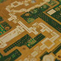
Mixed dielectric Rogers PCB
Mixed dielectric Rogers PCB Manufacturing, FR4 and Rogers Series materials Mixed PCB, Rogers different type materials Series Mixed PCB, or other types PCB Mixed dielectric PCB Vendor. we offer HDI PCBs from 4 layer to 108 layers. High quality and fast shiping time.
Mixed Dielectric Rogers PCBs are advanced printed circuit boards (PCBs) engineered with laminates from Rogers Corporation, a renowned manufacturer of high-performance materials. These PCBs utilize a combination of dielectric materials with varying properties, meticulously tailored to meet the stringent demands of high-frequency applications. By integrating distinct dielectric constants within the board’s construction, Mixed Dielectric Rogers PCBs excel in maintaining signal integrity, minimizing loss, and optimizing performance across a broad frequency spectrum. They find extensive use in sophisticated electronic systems, including RF circuits, microwave technologies, antennas, and wireless communication devices, where reliability and precision are paramount. With superior electrical characteristics and thermal stability compared to traditional FR-4 materials, Mixed Dielectric Rogers PCBs offer engineers unparalleled flexibility in designing cutting-edge solutions for today’s rapidly evolving technological landscape. As a cornerstone of modern electronics, these PCBs empower innovations in telecommunications, aerospace, medical devices, and beyond, driving progress and shaping the future of interconnected systems.
What is a Mixed Dielectric Rogers PCB?
We are a professional Mixed dielectric Rogers PCB manufacturing supplier, we mainly produce ultra-small bump pitch substrate, ultra-small trace and spacing packaging substrate and PCBs.
A Mixed Dielectric Rogers PCB refers to a printed circuit board (PCB) manufactured using materials from Rogers Corporation, a company known for producing high-performance laminates for electronic circuits. In this context, “mixed dielectric” implies that the PCB incorporates layers made from different dielectric materials.
Dielectric materials are insulators used to separate conductive layers in a PCB. Different dielectric materials have varying electrical properties, such as permittivity (or dielectric constant), loss tangent, and thermal conductivity. By using mixed dielectric materials, designers can tailor the electrical characteristics of different sections of the PCB to meet specific performance requirements.
Rogers PCBs are often used in high-frequency applications, such as RF (radio frequency) circuits, microwave circuits, and antennas, where signal integrity and minimal loss are critical. The choice of dielectric materials, along with the design and fabrication techniques, can significantly impact the performance of these circuits in terms of signal transmission, impedance control, and thermal management.
Overall, a Mixed Dielectric Rogers PCB provides designers with the flexibility to optimize the electrical properties of different portions of the PCB to achieve desired performance goals, particularly in high-frequency electronic systems.
What are the Mixed Dielectric Rogers PCB Design Guidelines?
Designing a Mixed Dielectric Rogers PCB involves considering various factors to ensure optimal performance and reliability, especially in high-frequency applications. Here are some general guidelines:
- Material Selection: Choose appropriate Rogers Corporation laminate materials for your specific application requirements. Rogers offers a range of laminates with different dielectric constants, loss tangents, and thermal properties. Select materials that match your desired electrical performance and frequency range.
- Layer Stackup Design: Design the layer stackup carefully to achieve controlled impedance and signal integrity. Place layers with similar dielectric constants adjacent to each other to minimize impedance variations. Consider the sequence of dielectric layers and signal layers to optimize signal propagation and minimize losses.
- Signal Routing and Transmission Lines: Follow best practices for high-frequency signal routing. Use controlled impedance transmission lines to maintain signal integrity and minimize reflections. Ensure consistent trace widths, spacing, and impedance throughout the PCB layout.
- Grounding and Power Distribution: Implement a solid grounding scheme to minimize ground loops and noise. Use dedicated ground planes and split planes where necessary to separate analog and digital ground regions. Optimize power distribution to minimize voltage drops and ensure stable power delivery to all components.
- Component Placement: Carefully place components on the PCB layout to minimize signal distortion and interference. Position high-speed components closer to each other to reduce trace lengths and minimize signal propagation delays. Follow thermal management guidelines to prevent hotspots and ensure proper component cooling.
- EMI/EMC Considerations: Design the PCB layout to minimize electromagnetic interference (EMI) and ensure compliance with electromagnetic compatibility (EMC) standards. Use proper shielding techniques, such as grounded copper pours and shielding cans, to contain electromagnetic emissions and prevent interference with other nearby circuits.
- Manufacturability: Consider manufacturability aspects during the design phase to ensure ease of fabrication and assembly. Follow industry-standard design rules and guidelines to avoid manufacturability issues such as solder mask registration errors, etching problems, and drilling misalignments.
- Thermal Management: Pay attention to thermal management to prevent overheating of critical components. Ensure proper thermal vias, heatsinks, and thermal relief pads to dissipate heat effectively and maintain stable operating temperatures.
- Simulation and Testing: Use simulation tools to validate the design and predict the performance of the Mixed Dielectric Rogers PCB. Perform signal integrity analysis, power integrity analysis, and thermal simulations to identify and address potential issues before fabrication. Conduct thorough testing, including impedance measurements and signal integrity testing, to verify the PCB’s performance.
By following these guidelines, designers can create Mixed Dielectric Rogers PCB layouts that meet the stringent requirements of high-frequency applications while ensuring reliable performance and manufacturability.
Mixed dielectric Rogers PCB
What is the Mixed Dielectric Rogers PCB Fabrication Process?
The fabrication process for a Mixed Dielectric Rogers PCB involves several steps, similar to the fabrication of other types of printed circuit boards. Here’s an overview of the typical fabrication process:
- Design Preparation: The fabrication process begins with the preparation of the PCB design files. Designers use PCB design software to create the layout, including the layer stackup, component placement, signal routing, and any special requirements specific to the Mixed Dielectric Rogers PCB.
- Material Selection: Select the appropriate Rogers Corporation laminates for the PCB based on the design requirements, such as dielectric constants, loss tangents, and thermal properties. Different layers may require different laminate materials to achieve the desired electrical performance.
- Layer Stackup: Determine the layer stackup configuration based on the design specifications. Arrange the dielectric layers and conductive layers in the desired sequence, taking into account impedance control and signal integrity requirements. Consider any mixed dielectric regions and their placement within the stackup.
- Preparation of Copper Clad Laminates: Prepare the copper clad laminates by cutting them to the required size and cleaning them to remove any contaminants. Apply a thin layer of adhesive to bond the copper foil to the dielectric substrate.
- 5. Circuit Patterning: Transfer the PCB design onto the copper clad laminates through a process called patterning. This typically involves applying a photosensitive resist material to the copper surface, exposing it to UV light through a photomask with the PCB pattern, and developing the resist to reveal the desired copper traces.
- Etching: Etch away the unwanted copper using chemical etchants, leaving behind the circuit traces and features defined by the resist pattern. The etching process ensures that the copper traces are precisely aligned with the design specifications.
- Drilling: Drill holes for through-hole components and vias using CNC drilling machines. Vias are plated with copper to establish electrical connections between different layers of the PCB.
- Plating and Surface Finishing: Plate the PCB with a thin layer of metal, typically copper, to improve solderability and protect the exposed copper surfaces. Apply surface finish coatings such as HASL (Hot Air Solder Leveling), ENIG (Electroless Nickel Immersion Gold), or immersion silver to protect the PCB from oxidation and provide a reliable solder joint.
- Final Inspection: Inspect the fabricated PCBs for any defects or manufacturing errors. Perform electrical tests, such as continuity checks and impedance measurements, to verify the integrity of the circuits.
- Routing and Profiling: Route individual PCBs from the larger panel and profile them to their final dimensions using CNC routing or milling machines.
- Quality Assurance: Conduct a final quality assurance check to ensure that the fabricated PCBs meet the required specifications and standards.
- Packaging and Shipping: Package the finished PCBs securely for shipment to the assembly facility or end users.
Throughout the fabrication process, it’s essential to maintain strict quality control measures to ensure the reliability and performance of the Mixed Dielectric Rogers PCBs. Additionally, adherence to industry standards and best practices helps minimize errors and defects during fabrication.
How do you manufacture a Mixed Dielectric Rogers PCB?
Manufacturing a Mixed Dielectric Rogers PCB involves specialized processes due to the use of high-performance laminates from Rogers Corporation and the need to maintain precise electrical properties across different dielectric materials. Here’s a general overview of the manufacturing process:
- Design Preparation: Begin with the PCB design phase, where the circuit schematic is translated into a physical layout using PCB design software. During this phase, designers specify the layer stackup, component placement, routing, and any special requirements related to mixed dielectric materials.
- Material Selection: Choose the appropriate Rogers Corporation laminates based on the design requirements, such as dielectric constants, loss tangents, and thermal properties. Different layers may require different laminate materials to achieve the desired electrical performance. Consult with Rogers Corporation for guidance on material selection.
- Layer Stackup Design: Design the layer stackup according to the specifications, considering the placement of mixed dielectric layers within the stackup. Ensure that the layer stackup configuration meets the impedance control and signal integrity requirements of the design.
- Preparation of Copper Clad Laminates: Prepare the copper clad laminates by cutting them to the required size and cleaning them to remove any contaminants. Apply a thin layer of adhesive to bond the copper foil to the dielectric substrate, following the manufacturer’s instructions.
- Circuit Patterning: Transfer the PCB design onto the copper clad laminates using photolithography or other patterning techniques. This involves applying a photosensitive resist material to the copper surface, exposing it to UV light through a photomask with the PCB pattern, and developing the resist to reveal the desired copper traces.
- Etching: Etch away the unwanted copper using chemical etchants, leaving behind the circuit traces and features defined by the resist pattern. Ensure precise alignment of the copper traces with the design specifications.
- Drilling: Drill holes for through-hole components and vias using precision CNC drilling machines. Vias are plated with copper to establish electrical connections between different layers of the PCB.
- Plating and Surface Finishing: Plate the PCB with a thin layer of metal, typically copper, to improve solderability and protect the exposed copper surfaces. Apply surface finish coatings such as HASL, ENIG, or immersion silver to protect the PCB from oxidation and provide a reliable solder joint.
- Final Inspection and Testing: Inspect the fabricated PCBs for any defects or manufacturing errors. Perform electrical tests, such as continuity checks and impedance measurements, to verify the integrity of the circuits. Ensure that the electrical properties of the mixed dielectric regions meet the desired specifications.
- Routing and Profiling: Route individual PCBs from the larger panel and profile them to their final dimensions using CNC routing or milling machines.
- Quality Assurance: Conduct a final quality assurance check to ensure that the fabricated PCBs meet the required specifications and standards for mixed dielectric Rogers PCBs.
- Packaging and Shipping: Package the finished PCBs securely for shipment to the assembly facility or end users.
Throughout the manufacturing process, it’s crucial to maintain strict quality control measures and adhere to industry standards to ensure the reliability and performance of the Mixed Dielectric Rogers PCBs. Collaboration with Rogers Corporation and other specialized suppliers may be necessary to address specific manufacturing challenges related to mixed dielectric materials.
How much should a Mixed Dielectric Rogers PCB cost?
The cost of a Mixed Dielectric Rogers PCB can vary widely depending on several factors, including:
- Board Size: Larger PCBs typically cost more due to increased material usage and manufacturing complexity.
- Layer Count: The number of layers in the PCB affects the fabrication and assembly costs. Mixed Dielectric Rogers PCBs may have complex layer stackups, which can contribute to higher costs.
- Material Selection: The choice of Rogers Corporation laminates and other materials can significantly impact the cost. High-performance laminates with specific electrical properties may be more expensive than standard FR-4 materials.
- Surface Finish: Different surface finish options, such as HASL, ENIG, or immersion silver, have varying costs.
- Copper Weight: Thicker copper layers or heavier copper weight can increase material costs.
- Trace Width and Spacing: Tighter tolerances for trace width and spacing may require more precise manufacturing processes, which can add to the cost.
- Complexity of Design: PCBs with intricate layouts, fine pitch components, and dense routing may require more time and labor during fabrication, leading to higher costs.
- Quantity: Economies of scale apply, meaning higher quantities typically result in lower per-unit costs due to efficiencies in production.
- Lead Time: Expedited manufacturing or shorter lead times may incur additional fees.
- Additional Services: Optional services such as electrical testing, panelization, and special packaging can add to the overall cost.
To get an accurate cost estimate for a Mixed Dielectric Rogers PCB, it’s best to consult with PCB manufacturers or suppliers directly. They can provide quotes based on your specific design requirements, including material selection, layer count, board size, and quantity. Additionally, you may consider obtaining quotes from multiple suppliers to compare pricing and services.
What is the Mixed Dielectric Rogers PCB base material?
The base material used in a Mixed Dielectric Rogers PCB typically consists of high-performance laminates manufactured by Rogers Corporation. Rogers offers a range of laminates specifically designed for high-frequency applications, including those requiring mixed dielectric properties.
Some commonly used base materials for Mixed Dielectric Rogers PCBs from Rogers Corporation include:
- RO3000® Series: This series includes high-frequency laminates with low dielectric loss, designed for applications such as RF and microwave circuits. Examples include RO3003™, RO3006™, and RO3010™ laminates.
- RO4000® Series: These laminates offer excellent electrical performance over a broad frequency range and are suitable for high-speed digital and RF/microwave applications. Examples include RO4003C™ and RO4350B™ laminates.
- RO4400™ Series: This series includes laminates with enhanced thermal conductivity for applications requiring efficient heat dissipation. Examples include RO4403™ and RO4450™ laminates
- RO6000® Series: These laminates are designed for demanding high-frequency applications, offering low dielectric constant and low loss. Examples include RO6002™ and RO6035™ laminates.
These base materials from Rogers Corporation are engineered to provide consistent electrical properties, thermal performance, and mechanical stability, making them suitable for Mixed Dielectric Rogers PCBs where precise control over dielectric properties is necessary. The choice of base material depends on the specific requirements of the PCB design, including frequency range, signal integrity, thermal management, and overall performance objectives.
Which company makes Mixed Dielectric Rogers PCBs?
Mixed Dielectric Rogers PCBs are manufactured by Rogers Corporation. Rogers Corporation is a well-known company specializing in the production of high-performance printed circuit board (PCB) materials, widely used in the high-frequency electronic field. The company offers a variety of high-performance laminates, including the RO3000 series, RO4000 series, RO4400 series, and RO6000 series, which exhibit excellent electrical properties, thermal performance, and mechanical stability, making them highly suitable for manufacturing Mixed Dielectric Rogers PCBs.
Our company is also capable of producing Mixed Dielectric Rogers PCBs. As a professional PCB manufacturer, we have advanced production equipment and a skilled technical team capable of customizing and producing high-quality Mixed Dielectric Rogers PCBs according to customer requirements and design specifications. We employ advanced processes and strict quality control procedures to ensure that every product meets the highest standards.
With experienced engineers and technical personnel, our company provides professional technical support and consultation services to our customers. We prioritize communication and collaboration with customers to ensure that we understand and meet their needs. Whatever type of Mixed Dielectric Rogers PCB our customers require, we are committed to providing them with the highest quality products and services.
By choosing our company as your supplier of Mixed Dielectric Rogers PCBs, you can rest assured that you will receive high-quality, reliable, and cost-effective products to meet your project requirements and achieve success. We are dedicated to building long-term partnerships with our customers and providing them with continuous support and service.
What are the 7 qualities of good customer service?
Good customer service is essential for building positive relationships with customers and ensuring their satisfaction. Here are seven qualities that characterize good customer service:
- Responsiveness: Responding promptly to customer inquiries, requests, and concerns demonstrates that you value their time and are committed to addressing their needs in a timely manner.
- Empathy: Showing empathy involves understanding and acknowledging the customer’s emotions, concerns, and perspectives. Empathetic responses can help build trust and rapport with customers, even in challenging situations.
- Professionalism: Maintaining professionalism in all interactions with customers is crucial for creating a positive impression and instilling confidence in your company. This includes being courteous, respectful, and maintaining a positive attitude, regardless of the circumstances.
- Knowledgeability: Having a thorough understanding of your products or services allows you to provide accurate information and assistance to customers. Knowledgeable customer service representatives can answer questions, offer solutions, and guide customers effectively.
- Adaptability: Being adaptable means being flexible and resourceful in finding solutions to meet customers’ unique needs and preferences. It involves being willing to adjust strategies or approaches to accommodate different situations or customer preferences.
- Clear Communication: Communicating clearly and effectively is essential for ensuring that customers understand information, instructions, and solutions provided by your customer service team. Using simple language, active listening, and avoiding jargon can help facilitate clear communication.
- Consistency: Consistency in customer service standards and experiences across all channels and touchpoints is crucial for building trust and loyalty. Customers should receive consistent levels of service quality, responsiveness, and professionalism regardless of how they interact with your company.
By prioritizing these qualities in your customer service approach, you can enhance customer satisfaction, loyalty, and advocacy, ultimately contributing to the success and reputation of your business.
FAQs (Frequently Asked Questions)
What are Mixed Dielectric Rogers PCBs?
Mixed Dielectric Rogers PCBs are printed circuit boards (PCBs) that use laminates from Rogers Corporation with different dielectric constants in their construction. These PCBs are designed for high-frequency applications where precise control over electrical properties is crucial.
What are the benefits of using Mixed Dielectric Rogers PCBs?
Mixed Dielectric Rogers PCBs offer improved signal integrity, reduced loss, and enhanced performance in high-frequency circuits compared to traditional PCB materials. They allow designers to tailor the electrical characteristics of different portions of the PCB to meet specific requirements.
What types of applications are suitable for Mixed Dielectric Rogers PCBs?
Mixed Dielectric Rogers PCBs are commonly used in high-frequency applications such as RF (radio frequency) circuits, microwave circuits, antennas, radar systems, and wireless communication devices.
How do Mixed Dielectric Rogers PCBs differ from standard FR-4 PCBs?
Mixed Dielectric Rogers PCBs use specialized laminates from Rogers Corporation, which offer superior electrical performance and thermal stability compared to standard FR-4 materials. They are designed specifically for high-frequency applications and offer lower loss and improved signal integrity.
What factors should be considered when designing Mixed Dielectric Rogers PCBs?
Designers should consider factors such as material selection, layer stackup design, signal routing, impedance control, grounding, power distribution, thermal management, and compliance with electromagnetic interference (EMI) and electromagnetic compatibility (EMC) standards.
Can Mixed Dielectric Rogers PCBs be manufactured using standard PCB fabrication processes?
While Mixed Dielectric Rogers PCBs can be manufactured using standard PCB fabrication processes, specialized techniques may be required to achieve precise control over electrical properties and ensure high performance.
Are there any limitations or challenges associated with using Mixed Dielectric Rogers PCBs?
Some challenges associated with Mixed Dielectric Rogers PCBs include higher material costs compared to standard FR-4 materials, as well as the need for careful design and manufacturing processes to ensure optimal performance.
Where can I obtain Mixed Dielectric Rogers PCBs?
Mixed Dielectric Rogers PCBs can be obtained from reputable PCB manufacturers or suppliers that specialize in high-frequency PCBs. It’s essential to choose a supplier with experience in handling Rogers Corporation laminates and producing high-quality PCBs for your specific application requirements.