
Rogers RT5880 High Frequency PCB
Rogers RT5880 High Frequency PCB Manufacturer, Ro5880/RT5880 PCB and Mixed media laminated PCB production company, we offer HDI Rogers 5880 PCBs from 2 layer to 30 layers. Ro5880 Cavity High Frequency PCBs.
Rogers RT5880 High Frequency PCBs are renowned for their exceptional electrical performance and reliability in high-frequency applications. Engineered by Rogers Corporation, a global leader in advanced materials, RT5880 PCBs offer a low dielectric constant of approximately 2.20, ensuring minimal signal loss and consistent impedance control across a broad frequency range. With a low loss tangent and excellent thermal stability, RT5880 PCBs are ideal for demanding applications such as RF/microwave circuits, antennas, radar systems, and satellite communications. Their dimensional stability and ease of fabrication make them a preferred choice for engineers and designers seeking high-performance solutions. Whether in aerospace, telecommunications, automotive, or other industries, Rogers RT5880 PCBs deliver unmatched quality and precision, enabling innovation and reliability in critical high-frequency systems.
Rogers RT5880 High Frequency PCB
What is Rogers RT5880 High Frequency PCB?
The Rogers RT/duroid® 5880 high-frequency laminate is a type of printed circuit board (PCB) material designed for applications requiring excellent electrical performance at high frequencies. It’s commonly used in RF (radio frequency) and microwave circuits where signal integrity, low loss, and minimal impedance variation are critical.
RT/duroid 5880 is known for its low dielectric constant and low loss tangent, which means it can efficiently transmit high-frequency signals with minimal signal degradation. It offers stable electrical properties over a wide range of frequencies, making it suitable for various high-frequency applications such as antennas, radar systems, satellite communications, and high-speed digital communications.
This type of PCB material is typically used in industries like aerospace, defense, telecommunications, and high-speed digital computing, where reliable high-frequency performance is essential.
What are the Rogers RT5880 High Frequency PCB Design Guidelines?
Designing PCBs with Rogers RT/duroid 5880 involves adhering to specific guidelines to ensure optimal performance at high frequencies. Here are some general design guidelines for Rogers RT/duroid 5880 high-frequency PCBs:
- Stackup Design: The PCB stackup should be carefully designed to achieve the desired impedance and signal integrity. This typically involves placing the RT/duroid 5880 material between layers with appropriate ground planes for signal integrity and impedance control.
- Impedance Control: Maintain controlled impedance traces to ensure signal integrity. Use trace widths, thicknesses, and spacing that match the desired characteristic impedance of the transmission lines. Impedance calculation tools specific to Rogers RT/duroid 5880 should be used for accurate results.
- Ground Plane: Ensure solid ground planes adjacent to signal layers to minimize electromagnetic interference (EMI) and maintain signal integrity. Ground vias should be strategically placed to provide low impedance return paths for high-frequency signals.
- Component Placement: Carefully place components to minimize trace lengths and reduce parasitic capacitance and inductance. Keep high-speed signal traces as short and direct as possible to minimize signal degradation.
- Routing Guidelines: Route high-frequency traces as straight and direct as possible to minimize signal reflections and losses. Use 45-degree or 90-degree angles instead of sharp angles to reduce impedance mismatches. Avoid crossing high-speed traces over split planes or other high-speed signals to minimize crosstalk.
- Via Design: Use high-quality plated-through vias with appropriate sizes and aspect ratios to minimize signal distortion and impedance changes. Via stubs should be minimized to reduce reflections and impedance variations.
- Dielectric Thickness: The dielectric thickness between signal layers should be carefully controlled to maintain consistent impedance. Follow the manufacturer’s recommendations for dielectric thickness and material properties.
- Thermal Management: Consider thermal management techniques to dissipate heat generated by high-power components or high-frequency operation. Heat sinks, thermal vias, and copper pours can help in managing thermal issues.
- Design for Manufacturability (DFM): Design the PCB with manufacturability in mind. Follow industry-standard DFM guidelines to ensure the design can be manufactured reliably and cost-effectively.
- Simulation and Testing:Use electromagnetic simulation tools to analyze and validate the PCB design for high-frequency performance. Prototyping and testing are essential to verify the design’s performance under real-world conditions.
By following these guidelines and working closely with the manufacturer’s specifications and recommendations, designers can create high-performance PCBs using Rogers RT/duroid 5880 material for high-frequency applications.
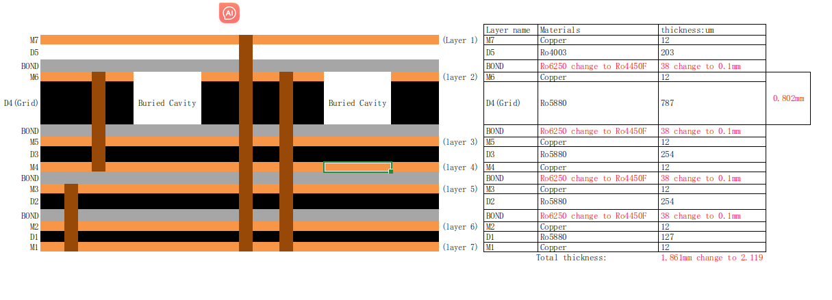
Rogers Cavity RT5880 PCB
What is the Rogers RT5880 High Frequency PCB Fabrication Process?
The fabrication process for Rogers RT/duroid 5880 high-frequency PCBs follows similar steps to standard PCB fabrication but with particular attention to high-frequency performance and material properties. Here’s a general overview of the fabrication process for Rogers RT/duroid 5880 PCBs:
- Material Preparation: Obtain Rogers RT/duroid 5880 laminate sheets in the required thickness and copper foil thickness. The laminate sheets should be stored in controlled environmental conditions to prevent moisture absorption and maintain material properties.
- Panelization: If multiple PCBs are to be fabricated on a single panel, the individual board designs are arranged in a panel layout. Panelization helps optimize material usage and facilitates the manufacturing process.
- Copper Cladding: Apply copper foil to both sides of the RT/duroid 5880 laminate sheets using a lamination process. The copper foil thickness should be chosen based on the specific requirements of the PCB design.
- Drilling: Holes for through-hole components and vias are drilled into the panel using precision CNC drilling machines. The drill bits used should be suitable for drilling through the laminate and copper layers without causing delamination or damage.
- Desmear and Etching: After drilling, the panel undergoes a desmear process to remove any residual drilling debris and roughen the copper surface for better adhesion of the photoresist. Next, a photoresist layer is applied to the copper surfaces, exposed to UV light through a photomask, and developed to define the circuit traces and pads. The panel then undergoes etching to remove excess copper and define the copper traces and features.
- Plating: Through-hole vias and plated through-holes are electroplated with copper to provide electrical connectivity between layers. This process involves the deposition of copper into the drilled holes and onto the surface of the panel to build up the required copper thickness.
- Surface Finish: Apply a surface finish to protect the exposed copper surfaces and facilitate soldering. Common surface finish options include immersion gold, HASL (Hot Air Solder Leveling), ENIG (Electroless Nickel Immersion Gold), OSP (Organic Solderability Preservative), and others, chosen based on the specific requirements of the application.
- Silkscreen: Optionally, apply a silkscreen layer for component markings, polarity indicators, and other visual information. The silkscreen layer is typically applied using a screen printing process with ink that withstands the PCB assembly process.
- Final Inspection: Perform a final inspection of the fabricated PCBs to ensure they meet the specified design requirements, dimensional tolerances, and quality standards. Automated optical inspection (AOI) and electrical testing may be conducted to detect any defects or issues.
- Routing and Separation: After inspection, the panel is routed to separate individual PCBs if they were panelized earlier. The separation process may involve mechanical routing, milling, or scoring depending on the panelization method and design requirements.
- Quality Assurance: Conduct quality assurance checks to verify the dimensional accuracy, electrical continuity, and overall quality of the fabricated PCBs before packaging and shipment.
Throughout the fabrication process, it’s essential to follow best practices for handling and processing Rogers RT/duroid 5880 material to maintain its high-frequency performance and material properties. Additionally, adherence to industry standards and guidelines ensures the reliability and functionality of the finished PCBs.
How do you manufacture a Rogers RT5880 High Frequency PCB?
Manufacturing a Rogers RT/duroid 5880 high-frequency PCB involves several steps, similar to the fabrication process of standard PCBs, but with specific considerations for high-frequency performance and material properties. Here’s a general overview of the manufacturing process:
- Material Selection: Choose Rogers RT/duroid 5880 laminate sheets with the appropriate thickness and copper foil configuration based on the design requirements.
- Preparation: Ensure that the RT/duroid 5880 laminate sheets are stored in controlled environmental conditions to prevent moisture absorption and maintain material properties.
- Panelization: Arrange the individual PCB designs into a panel layout if multiple PCBs will be fabricated on a single panel. Panelization optimizes material usage and facilitates the manufacturing process.
- Copper Cladding: Apply copper foil to both sides of the RT/duroid 5880 laminate sheets using a lamination process. The copper foil thickness should be chosen based on the specific requirements of the PCB design.
- Drilling: Precision CNC drilling machines are used to drill holes for through-hole components and vias. The drill bits must be suitable for drilling through the laminate and copper layers without causing delamination or damage.
- Desmear and Etching: After drilling, the panel undergoes a desmear process to remove any residual drilling debris and roughen the copper surface for better adhesion of the photoresist. Next, a photoresist layer is applied to the copper surfaces, exposed to UV light through a photomask, and developed to define the circuit traces and pads. The panel then undergoes etching to remove excess copper and define the copper traces and features.
- Plating: Electroplate the through-hole vias and plated through-holes with copper to provide electrical connectivity between layers. This process involves the deposition of copper into the drilled holes and onto the surface of the panel to build up the required copper thickness.
- Surface Finish: Apply a surface finish to protect the exposed copper surfaces and facilitate soldering. Common surface finish options include immersion gold, HASL (Hot Air Solder Leveling), ENIG (Electroless Nickel Immersion Gold), OSP (Organic Solderability Preservative), and others, chosen based on the specific requirements of the application.
- Silkscreen: Optionally, apply a silkscreen layer for component markings, polarity indicators, and other visual information. The silkscreen layer is typically applied using a screen printing process with ink that withstands the PCB assembly process.
- Final Inspection: Perform a final inspection of the fabricated PCBs to ensure they meet the specified design requirements, dimensional tolerances, and quality standards. Automated optical inspection (AOI) and electrical testing may be conducted to detect any defects or issues.
- Routing and Separation: After inspection, the panel is routed to separate individual PCBs if they were panelized earlier. The separation process may involve mechanical routing, milling, or scoring depending on the panelization method and design requirements.
- Quality Assurance: Conduct quality assurance checks to verify the dimensional accuracy, electrical continuity, and overall quality of the fabricated PCBs before packaging and shipment.
Throughout the manufacturing process, it’s crucial to handle and process the Rogers RT/duroid 5880 material with care to maintain its high-frequency performance and material properties. Adherence to industry standards and guidelines ensures the reliability and functionality of the finished PCBs.
How much should a Rogers RT5880 High Frequency PCB cost?
The cost of a Rogers RT/duroid 5880 high-frequency PCB can vary widely depending on several factors, including:
- Board Size and Complexity: Larger PCBs with more complex designs will generally cost more due to increased material usage, longer manufacturing times, and potentially higher reject rates during fabrication.
- Layer Count: The number of layers in the PCB affects the fabrication complexity and material costs. High-layer-count PCBs typically cost more than single or double-layer boards.
- Material Thickness: Rogers RT/duroid 5880 laminate is available in various thicknesses, and thicker materials may cost more due to increased material usage.
- Copper Weight: The thickness of the copper foil used in the PCB affects both material costs and manufacturing processes. Heavier copper weights generally result in higher costs.
- Surface Finish: Different surface finish options, such as immersion gold or ENIG, have different costs associated with them. Specialty surface finishes may add to the overall PCB cost.
- Trace Width and Spacing: Tighter tolerances for trace width and spacing, especially for controlled impedance traces, may increase fabrication costs due to more precise manufacturing requirements.
- Drilling Complexity: PCBs with high-density components or fine-pitch components require more precise drilling, which can increase manufacturing costs.
- Volume and Order Quantity: Larger production volumes typically result in lower per-unit costs due to economies of scale. However, prototype or small-batch orders may incur higher costs per unit.
- Lead Time: Expedited manufacturing or quick-turn services often come with additional costs compared to standard lead times.
- Supplier and Location: PCB fabrication costs can vary between different manufacturers and regions due to differences in labor costs, overhead expenses, and quality standards.
Given these factors, it’s challenging to provide an exact cost without specific details about the PCB’s design requirements and manufacturing specifications. It’s best to consult with PCB manufacturers or suppliers to obtain accurate price quotes based on your project’s needs.
What is the Rogers RT5880 High Frequency PCB base material?
Rogers RT5880 is a high-frequency PCB material manufactured by Rogers Corporation. It belongs to the family of ceramic-filled PTFE (Polytetrafluoroethylene) composites, which are known for their excellent electrical properties and stability at high frequencies.
The base material of Rogers RT5880 typically consists of the following components:
- PTFE (Polytetrafluoroethylene): PTFE is the main polymer component of the material. It provides excellent dielectric properties, low loss tangent, and high thermal stability, making it suitable for high-frequency applications.
- Ceramic Fillers: Ceramic fillers, such as barium titanate or alumina, are added to the PTFE matrix to enhance the dielectric constant and maintain a consistent dielectric constant over a wide range of frequencies. These fillers also contribute to the dimensional stability and mechanical strength of the material.
- Glass Reinforcement (Optional): Some variants of Rogers RT5880 may include woven glass reinforcement for added mechanical strength and dimensional stability, especially in multilayer PCBs or applications with demanding mechanical requirements.
Overall, Rogers RT5880 combines the properties of PTFE with ceramic fillers to achieve a balance of high electrical performance, thermal stability, and mechanical integrity required for high-frequency PCB applications.
Which company makes Rogers RT5880 High Frequency PCBs?
Rogers RT5880 high-frequency PCBs are manufactured by Rogers Corporation, a company based in the United States. Rogers Corporation is a global engineering materials supplier with extensive experience in electronics, communications, aerospace, and other industries. They have developed various advanced high-performance materials used in manufacturing high-frequency PCBs and other electronic components, among which RT5880 is one of them.
Our company can also produce Rogers RT5880 high-frequency PCBs. As a professional PCB manufacturer, we have advanced production equipment and rich experience in producing high-quality PCB products according to customer requirements. Our engineering team has a deep technical background and rich experience, capable of providing customized solutions to ensure meeting specific customer needs.
In the production of Rogers RT5880 high-frequency PCBs, we will strictly follow manufacturing processes and standard operating procedures to ensure the highest level of product quality and performance. We will implement advanced material management and quality control systems to ensure that each PCB meets customer specifications and undergoes rigorous testing and inspection.
Through the Rogers RT5880 high-frequency PCBs produced by our company, customers can obtain high-performance and highly reliable circuit boards suitable for various high-frequency applications such as communication equipment, radar systems, satellite communications, etc. We are committed to providing customers with high-quality products and satisfactory services, working together with customers for mutual development.
What are the 7 qualities of good customer service?
Good customer service is characterized by several key qualities that help foster positive interactions and build strong relationships with customers. Here are seven qualities of good customer service:
- Empathy: Good customer service representatives demonstrate empathy by understanding and acknowledging the customer’s feelings, concerns, and needs. They put themselves in the customer’s shoes and strive to address their issues with genuine care and understanding.
- Responsiveness: Good customer service is prompt and responsive. Representatives should be available to assist customers in a timely manner, whether it’s answering inquiries, resolving issues, or providing support. Quick response times help customers feel valued and respected.
- Clarity: Clear communication is essential for good customer service. Representatives should communicate information in a straightforward and easy-to-understand manner, avoiding jargon or technical language that may confuse customers. Clear communication helps prevent misunderstandings and ensures that customers have a clear understanding of the situation.
- Professionalism: Good customer service is characterized by professionalism at all times. Representatives should maintain a professional demeanor, regardless of the situation, and conduct themselves with courtesy, respect, and integrity. Professionalism instills confidence in customers and fosters trust in the company.
- Problem-Solving Skills: Good customer service representatives possess strong problem-solving skills. They can effectively identify and analyze customer issues, develop appropriate solutions, and take proactive steps to resolve problems. Problem-solving skills enable representatives to address customer concerns efficiently and effectively.
- Flexibility: Good customer service requires flexibility and adaptability. Representatives should be willing to accommodate customer needs and preferences, even if it means going above and beyond standard procedures. Flexibility allows representatives to tailor their approach to meet the unique needs of each customer.
- Follow-Up: Following up with customers is an important aspect of good customer service. Representatives should follow up with customers after resolving an issue to ensure satisfaction and address any lingering concerns. Follow-up demonstrates care and commitment to customer satisfaction and helps build long-term relationships.
By embodying these qualities, businesses can deliver exceptional customer service experiences that leave a positive impression on customers and contribute to overall satisfaction and loyalty.
FAQs (Frequently Asked Questions)
What is Rogers RT5880 PCB material?
Rogers RT5880 is a high-frequency PCB material known for its excellent electrical properties, low loss tangent, and stability at microwave frequencies. It is commonly used in applications such as RF/microwave circuits, antennas, radar systems, and satellite communications.
What are the key features of Rogers RT5880 PCB material?
The key features of Rogers RT5880 PCB material include a low dielectric constant (typically around 2.20), low loss tangent, excellent thermal stability, dimensional stability, and ease of fabrication.
What are the advantages of using Rogers RT5880 PCB material?
Advantages of using Rogers RT5880 PCB material include high electrical performance, minimal signal loss, consistent impedance control, reliability, and suitability for high-frequency applications.
How does Rogers RT5880 compare to other PCB materials?
Compared to other PCB materials, Rogers RT5880 offers superior electrical performance and stability at high frequencies. It provides lower loss tangent and better thermal stability compared to standard FR-4 materials.
What are the typical applications of Rogers RT5880 PCBs?
Rogers RT5880 PCBs are used in a wide range of high-frequency applications, including communication systems, radar systems, satellite communications, automotive radar, aerospace systems, and high-speed digital designs.
What are the design guidelines for Rogers RT5880 PCBs?
Design guidelines for Rogers RT5880 PCBs include considerations for controlled impedance, signal integrity, ground plane design, trace geometry, via design, component placement, power distribution, thermal management, and design for manufacturability.